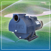
Pump sizing is essential when choosing the right pump for an irrigation application. Incorrect sizing can lead to low pumping efficiency and may negatively affect energy consumption and cost, or may result in the irrigation system not performing at all. The following simple steps will help you quickly find the performance required for the application so that you can select a pump that is best suited for the job.
Step One – Gallons Per Minute (GPM)
The first step in sizing a pump for irrigation is to determine the total Gallons Per Minute (GPM) required. To do this, you will need to know how many sprinkler heads will be utilized in the largest sprinkler zone. Each sprinkler head requires a specific GPM (this number can be found in the specifications for the sprinkler heads). Once you know the GPM each sprinkler head requires, multiply that number by the amount of sprinkler heads that are present in this zone. The product of these two numbers will give you the total GPM.
Step Two – Total Dynamic Head (TDH)
The second step in sizing a pump is to determine the Total Dynamic Head (TDH). The TDH is a calculation of the required pressure (PSI) for the irrigation system to operate efficiently and additional or lesser required pressures that the pump must perform to accommodate for the system set up. There are three factors in the system set up that can affect the amount of pressure the pump must produce – elevation change, suction lift or incoming pressure and friction loses.
Elevation change is determined by measuring the height change from the pump outlet to the highest point in the sprinkler system. This is the elevation that the pump has to push the water up.
Suction lift or incoming pressure relate to the intake side of the pump. Is the pump boosting the pressure of city water? That’s incoming pressure and the amount of incoming pressure would be subtracted from the total pressure required because that pressure already exists so the pump does not need to create it. Suction lift is the distance in height between the water level and the pump inlet. The pump needs to pull the water up from the water level.
Friction loss is created when the water moves through the pipework in the irrigation system. These losses are easily determined by using a Friction Loss Chart. On the Friction Loss Chart, find the desired GPM (from step one) at a velocity of 5’ per second (+1/-1), to find the most efficient pipe size for the system (if the pipe is already in place and will not be changed, you’ll need to look at the existing pipe size regardless of the efficiency). Identify the head loss feet for the type of pipe your system is using (most irrigation systems use PVC pipe). Multiply this number by the number of 100’ lengths in the largest pipe run (for example, if there is 300’, you would multiply by 3). Please note that valves, strainers, and fittings will contribute to losses. In this case, refer to manufacturer’s loss information and include in Friction Loss total.
Pounds per square inch (PSI) is the last part of the TDH equation and refers to the pressure required at the end of the line of the largest zone. To calculate PSI, use the instructions that come with your sprinkler heads. This number should be multiplied by 2.31, to give you the total PSI in feet, because all of the other variables in your equation are expressed in feet.
The Total Dynamic Head (in feet) will be calculated as:
PSI + Elevation change + Suction lift – pressure boost + friction loss = TDH
Step Three – Power and Water Supply
The final application aspects to consider when choosing a pump are the power and water supplies. Whether the pump will be electrical or gas driven and what power rating you will need will usually be based on what power source is available on site. If the water sources are dirty, filtration may be required (filters will affect your TDH due to friction losses).
Step Four – Using a Pump Curve
You now have the performance requirements for the application, which you will use to select a pump that will provide the required performance. A pump curve is set up with an X and Y axis – find your performance requirement on the axes to identify the pump that provides the required performance. If you find that the results are between two pumps, it is better to size up than to size down. Don’t forget to select a pump that uses the available power source and rating.
Our
pump data worksheets can really help to walk you through this process and provide a record of the information you gathered. If you have any trouble working through this process, please contact our pump experts for help.